- 제목: CRUMB
- 출시일:
- 개발자:
- 발행자:
Information about CRUMB is still incomplete. 이것을 사용하여 게임의 세부 정보를 입력할 수 있도록 도와주세요. 문의 양식.
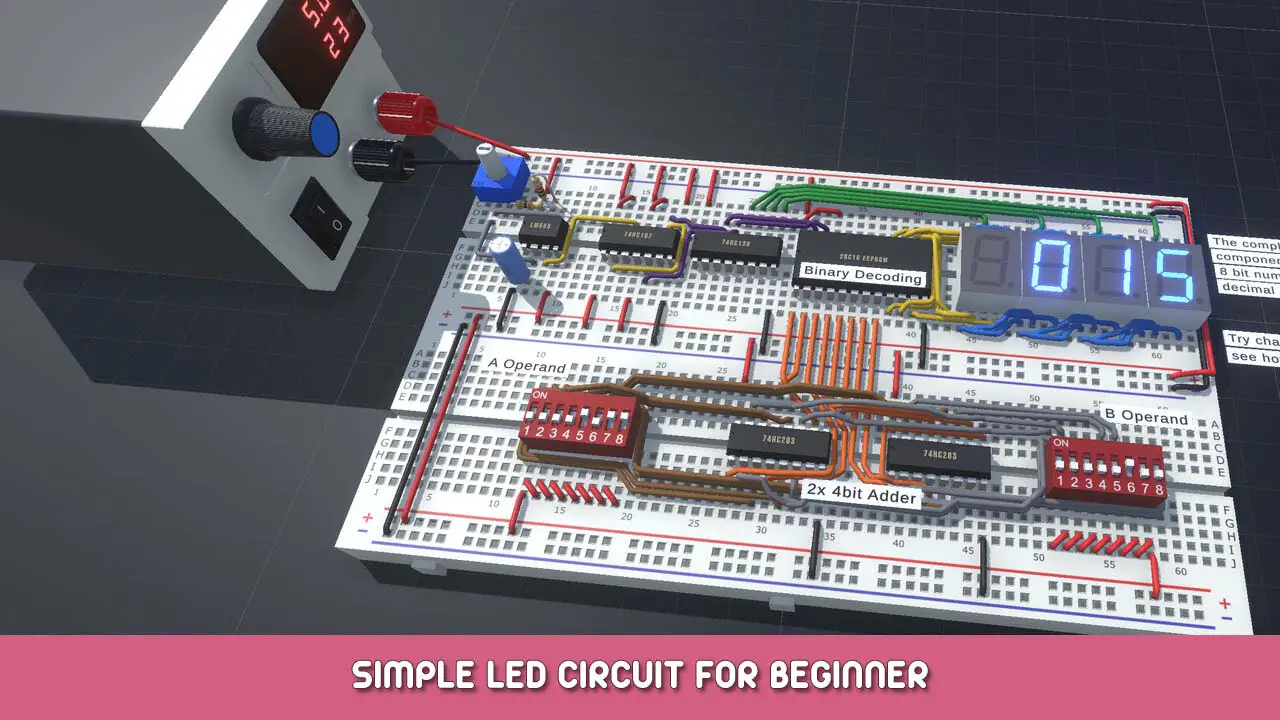
Simple circuit for beginner that don’t know how to build the circuit on the breadboard
개요
This is a simple walk-through guide for the beginner to learn how to use the breadboard to build a circuit based on your design. This guide will include:
- Understand the breadboard
- 준비
- Wire and components
- Power on
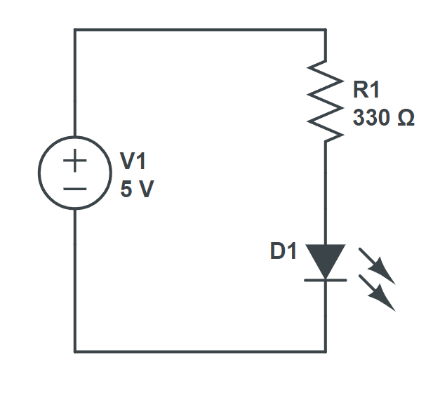
The circuit diagram for this guide is:
Understand the breadboard
먼저, before we start to build the circuit, we need to understand what is a breadboard?
Breadboard is very commonly used in the lab for building the
temporary circuit. By using a breadboard, soldering is not needed and is easier for the user to change the connections very quickly.
The first thing that we need to do is to attach the power rail to the top and bottom of the breadboard.

After attaching the power rail the breadboard should look like this.

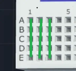
In the diagram above, you can see some green lines that represent the common connection (row and column).
예를 들어, the wire/connections inserted in A1 is
electrically connectedto B1, C1, D1, E1. This applies to the power rails as well.
준비
There are a few preparation steps we will usually take before start making connections. The very first thing to do is to connect the power rails.
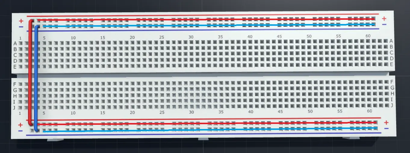
As you can see the (+) rail on top is connected to the bottom (+) rail. Same thing applies to the (-) rails. This is much
easier for us to make connections그리고
easier for the wire managementswhen circuit is getting more and more complicated.
둘째, If we have a lot of components, we need to plan the placement of the components. This is very simple but crucial step to ensure minimum wire crossing on the breadboard. But in this guide only a few wires are needed so it is not very significant.
Wire and components placement
먼저, we look back the circuit diagram.
The important thing we need to beware is the polarity of the components.
As you can see in this circuit diagram, 그만큼 (+) polarity of the
power sourceis connected to one of the terminals of the 330ohm
resistor.
Then another terminal of the
resistoris connected to the
anode(which is also refer to the positive terminal) ~의
주도의. 그만큼
cathode(negative terminal) ~의
주도의is connected to the (-) terminal of the
power source.
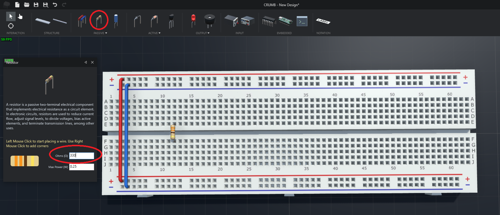
So we can now place the resistor first onto the breadboard. 이 경우, I place the resistor in hole E12 and F12. The resistance of the resistor is set as 330 ohm.
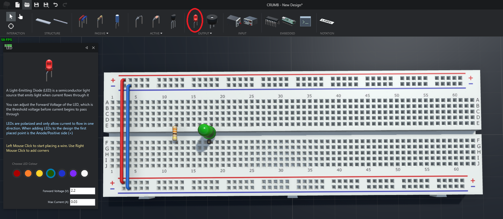
다음, I place the LED in hole
F18for anode (+) 그리고
E18for cathode (-).
중요한: Please look carefully for the anode (+) and cathode (-) pins of the LED !
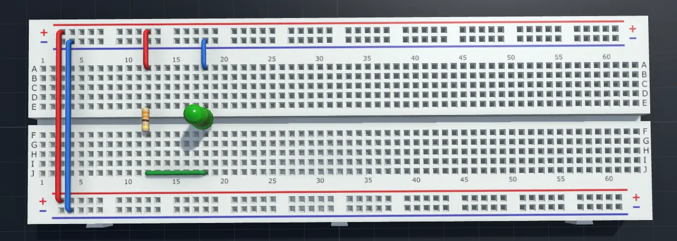
마지막으로, we need to connect each of the components (resistor and LED) to form a closed circuit.
You can compare the diagram below with the circuit diagram to understand better.
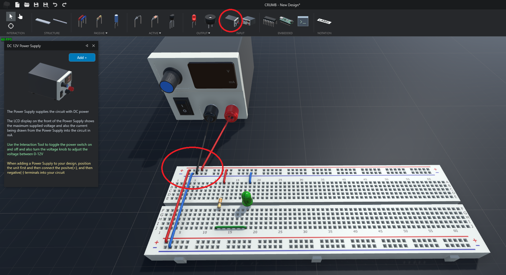
Power On
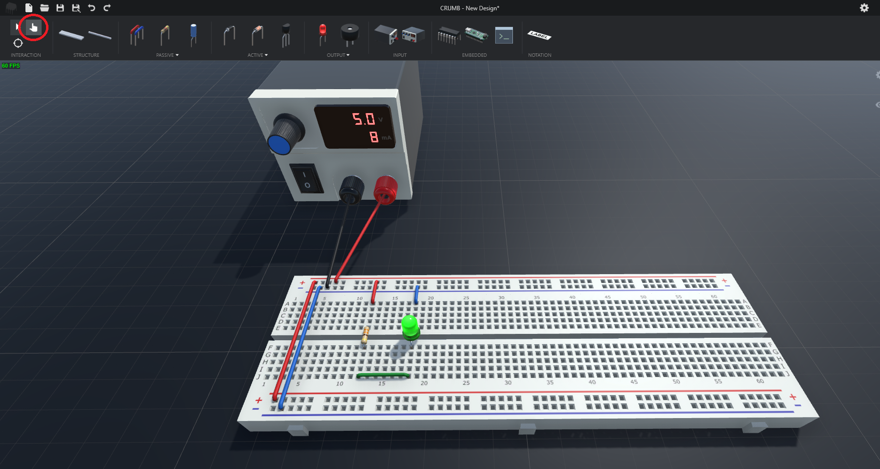
마지막으로, we need power supply to electrically turn on the the circuit. Based on the diagram below, you can see that the red terminal of the power supply is connected to the (+) power rail and black terminal is connected to the (-) power rail.
마지막으로, we can switch to the Interact tool and turn on the power supply.
잘하셨어요, you completed your very first mini project and hope you will enjoy this guide.
감사해요. =)
결론
Thanks for reading this guide until the end. Please comment below if you have any doubt or questions. It might look strange to you when you first time using the breadboard, but i am sure that you will do better and better after using it for several times. 감사합니다. =)