
In Stormworks, there isn’t a straightforward method to ascertain the transition from night to morning. Dennoch, by employing a bit of ingenuity, you can simulate a daylight sensor by leveraging one of the game’s less utilized components. I’m here to guide you through the process.
Theory and Materials
To effectively gauge environmental light levels in Stormworks, we need a means of measurement. The challenge lies in the absence of a direct method for quantifying light levels, and there exists only one component capable of exhibiting variability – the electrical system. Jedoch, it’s important to note that the fluctuations in this electrical output cannot be directly measured. Das heißt, we can still make use of this electrical aspect to create a simulated daylight sensor.
Through extensive testing, it has been observed that the electrical output from solar panels in the game is somewhat unreliable. Even with ample daylight remaining, they tend to cease producing a usable charge fairly early in the evening, necessitating an extension of the „sensor“ activation duration. Umgekehrt, they commence power generation quite early in the morning, implying a need to prolong their period of inactivity.
The solution I’ve devised is rather straightforward. It revolves around the utilization of solar panels, the sole in-game objects responsive to light levels, in conjunction with an electric motor. The motor’s revolutions per second (RPS) decrease as the incoming power diminishes and rise as the power input increases, assuming that the throttle level remains constant and the available power remains below the maximum consumption rate. While this partly resolves the delayed on/off issue due to the motor’s rotational momentum, it falls slightly short. Um dies anzugehen, I’ve introduced a flywheel into the setup, which I’ll elaborate on shortly. Zur Zeit, here’s a list of the components you’ll require:
- 5 Sonnenkollektoren
- 1 Microcontroller (2×2)
- 1 Modular Engine Clutch (1×1)
- 1 Modular Engine Flywheel (1×1)
- 1 Dial or Numeric Display (optional)
Component Layout
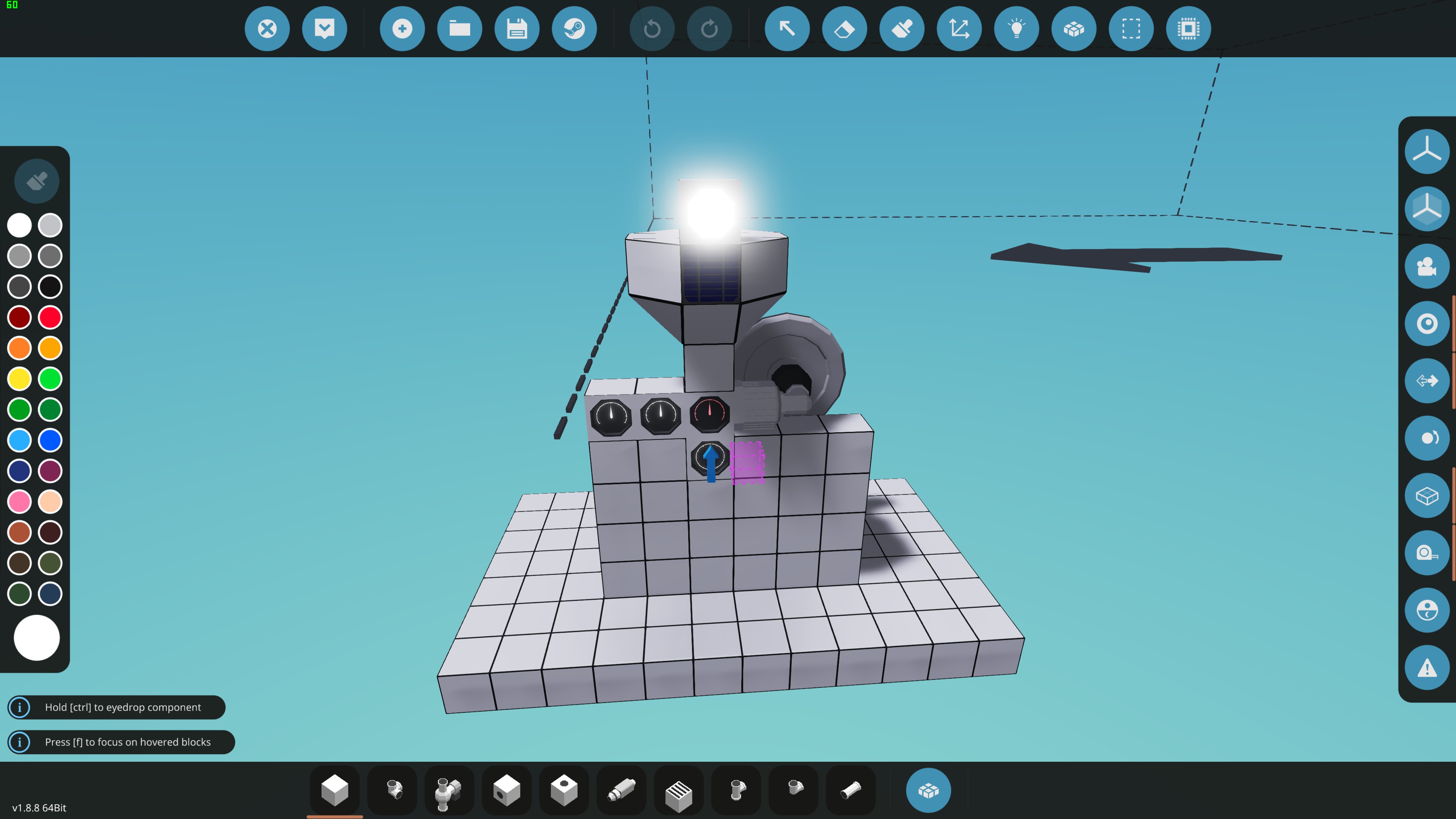
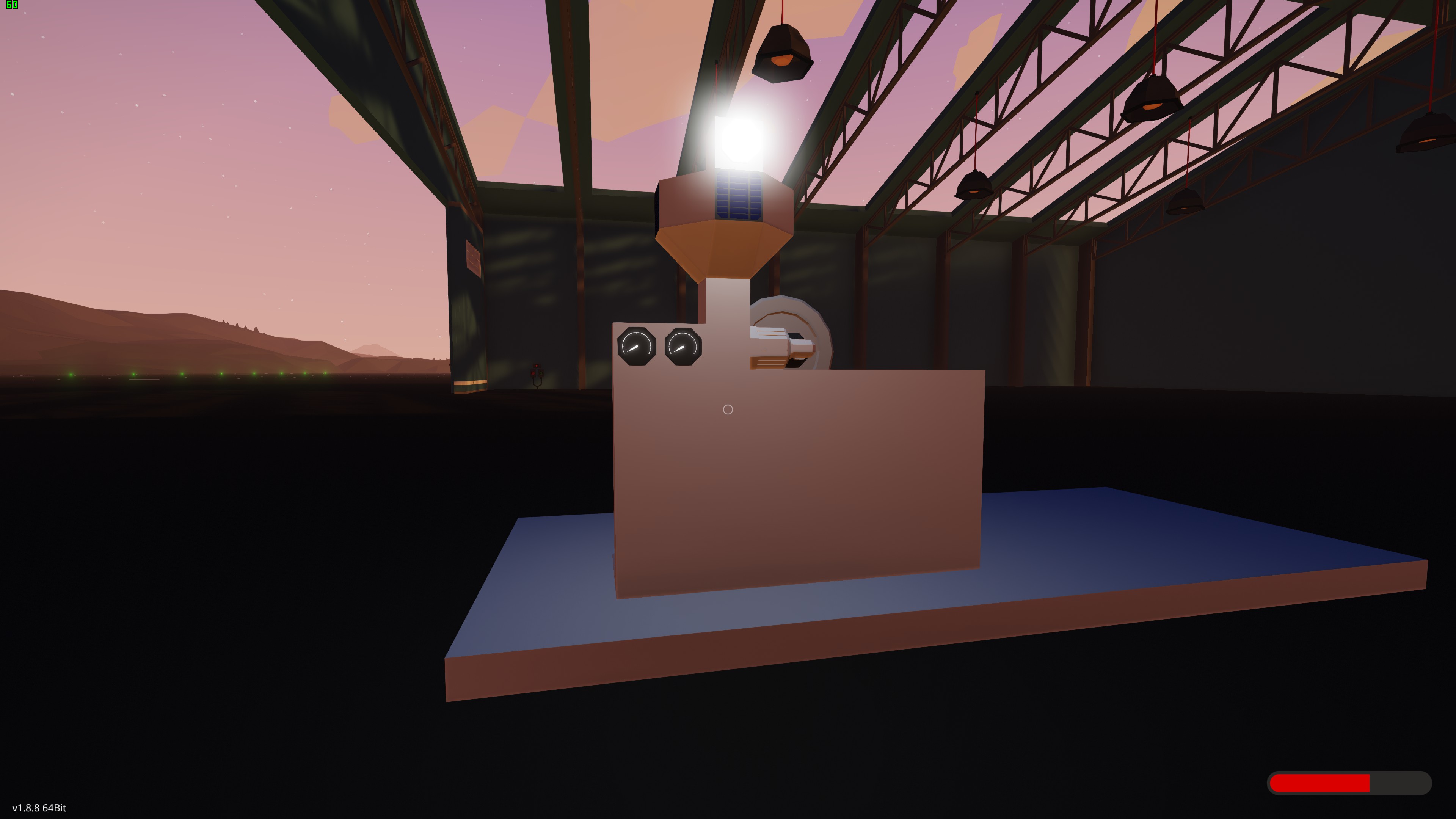
Based on the provided details, the electrical output of the solar panels in Stormworks is influenced by both the angle and the time of day. Folglich, I’ve positioned one panel facing the sky, while the remaining four have been evenly distributed on each horizontal face, oriented towards the horizon. It’s worth noting that these panels can be installed anywhere on the exterior of the creation, offering flexibility in their placement.
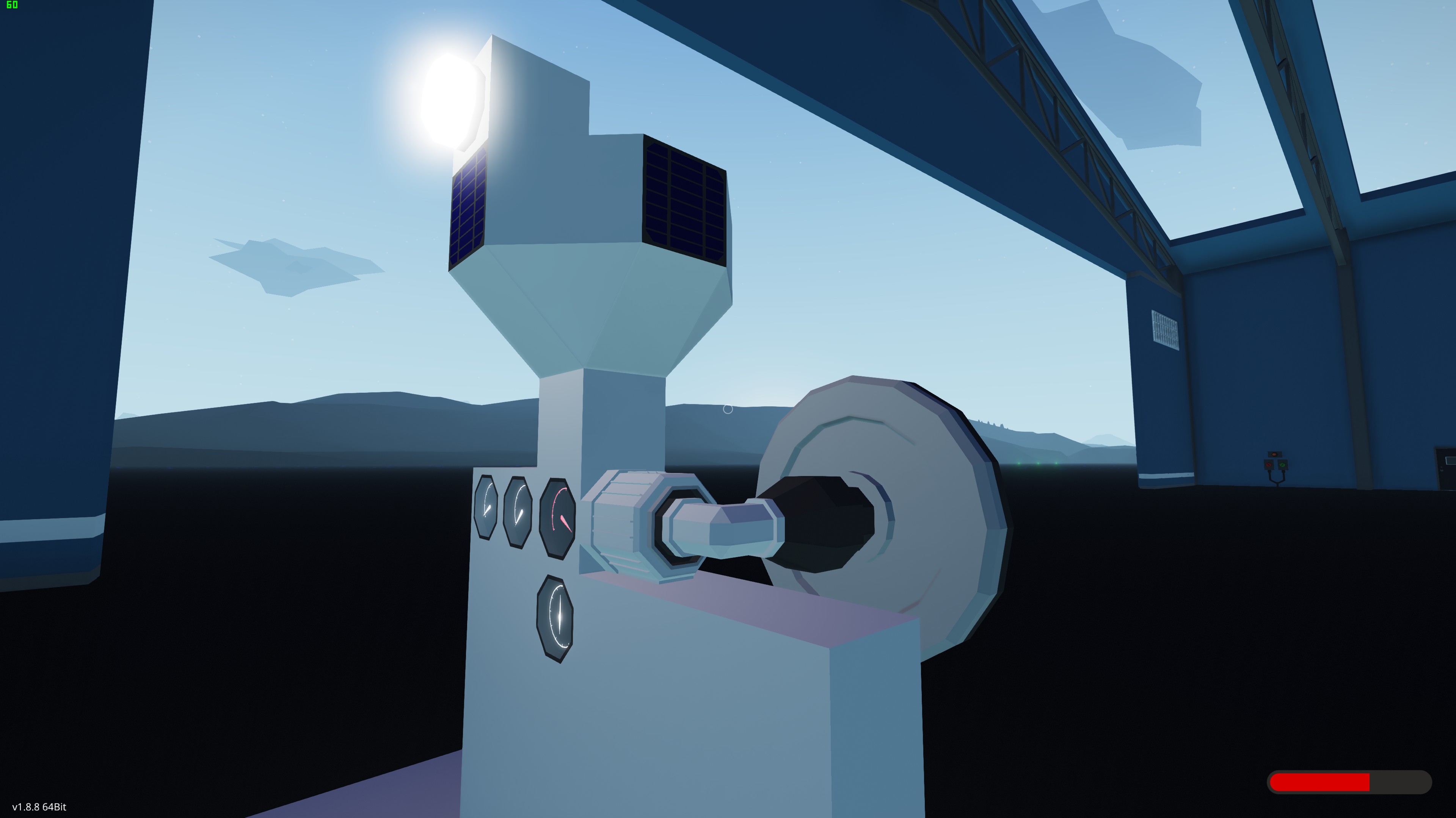
It’s important to mention that the motor can be situated in any suitable location. Jedoch, it’s crucial to establish connections correctly. The motor should be connected to the clutch (output end), und anschließend, the clutch should be linked to the flywheel. In the provided screenshot, a corner pipe was employed to establish the connection between the motor and the clutch (output end), while the flywheel is directly attached to the clutch (motor end). This arrangement ensures the proper functioning of the system.
Microcontroller
Design a 2×2 microcontroller system with four logic nodes: one for numerical input, one for logic output, and two for numerical output. The numerical input node is responsible for measuring the revolutions per second (RPS) of a flywheel, while the logic output node controls a system that needs activation either during the day or night, such as lighting. The two numerical output nodes serve for convenience, one regulating motor throttle and the other managing clutch pressure.
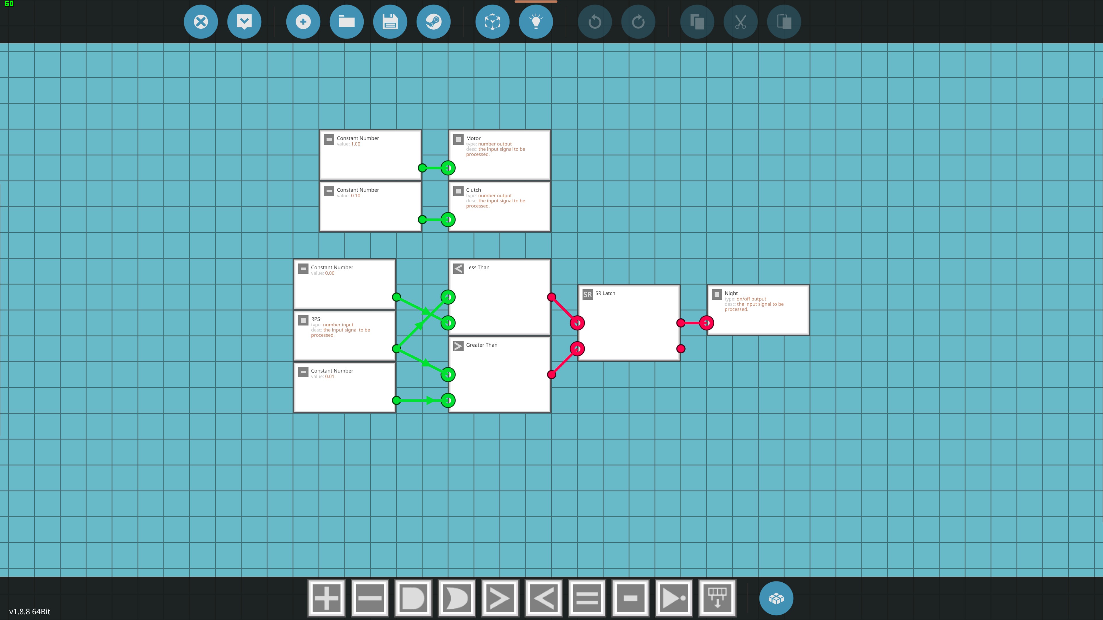
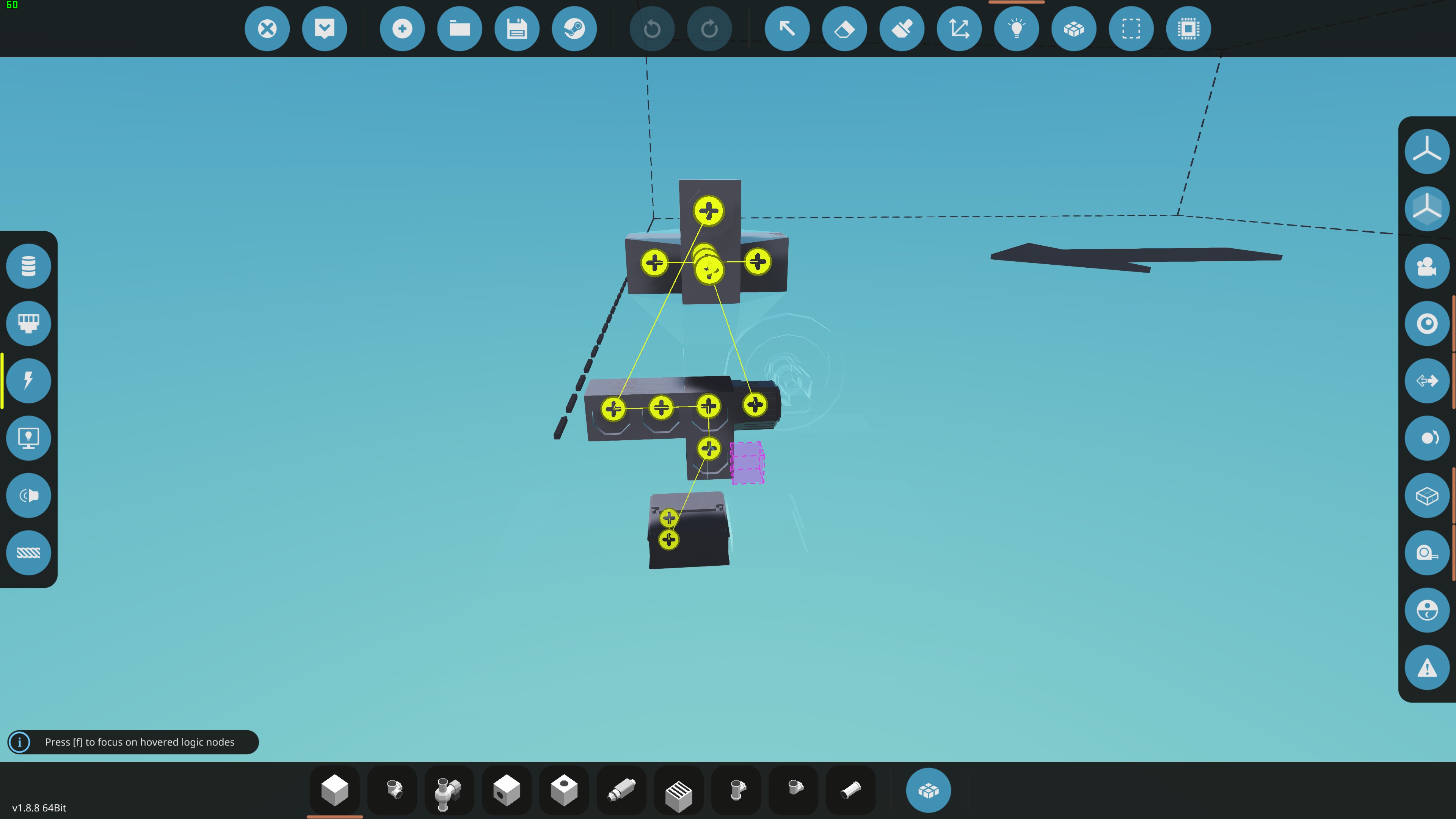
Jetzt, let’s detail the actual logic as described (a visual representation will follow):
- Connect a constant number block set to 1 to the numerical output node for motor throttle.
- Repeat the previous step for the clutch output node, but this time connect a constant number block with a value of 0.1.
- Integrate a less-than block and a greater-than block into the system. Connect the numerical input node to the A input of both recently added blocks. Proceed to include two constant number blocks, one for each of the B inputs. The specific values to assign to these blocks will require testing (details to be provided later).
- Add a set-reset block, utilizing the less-than block to set the latch and the greater-than block to reset the latch. Endlich, connect the latch output to the output logic node.
Logic and Electric
After configuring the microcontroller, the next step is to establish the necessary connections. Befolgen Sie diese Anweisungen:
- Connect the microcontroller to the motor, clutch, and the RPS sensor on the flywheel as required by the design.
- If applicable, connect the RPS output to the optional dial or display, which was mentioned earlier, for monitoring purposes.
- For the electric components, connect the solar panels together in the appropriate configuration. Ensure that the solar panels are then connected to the motor.
- Wichtig: Do not connect any part of the system to an external power grid. The entire system relies solely on its internal power generation, primarily from the solar panels. Connecting to an external power grid will disrupt the functionality of the system.
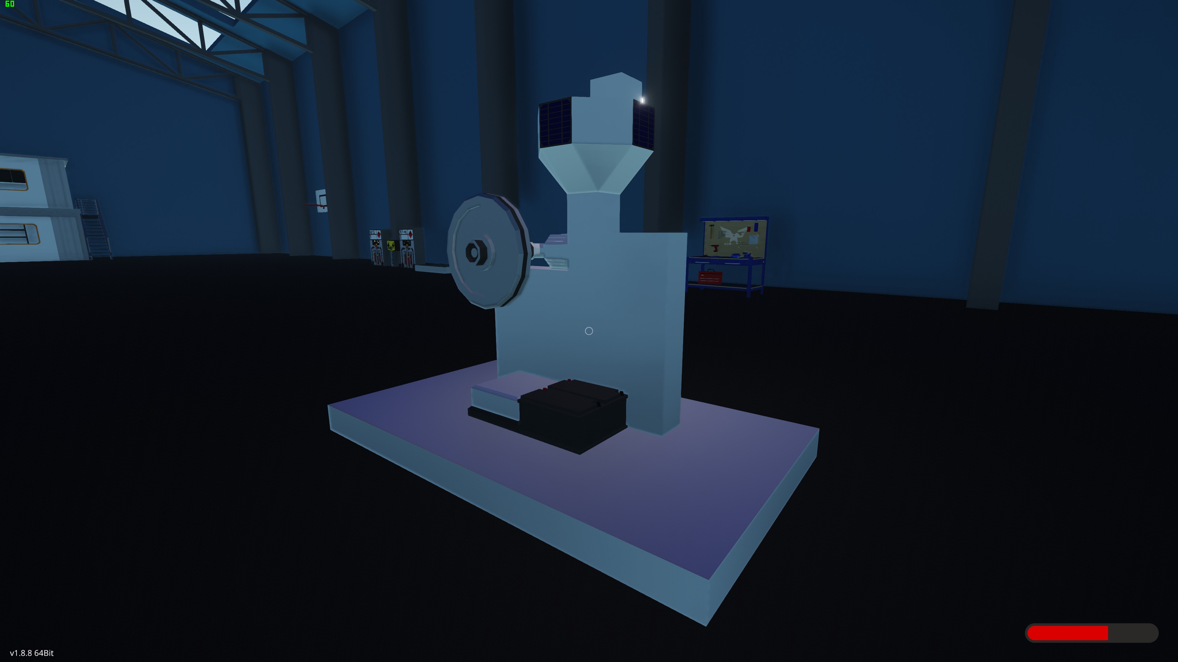
- Note that in your provided screenshot, the battery bank is isolated from the system. It should only be used to power specific components like lamps and the dial backlights, independent of the core system’s operation.
Testing For Values (Configuration)
The system should be fully installed, yet it requires configuration. If you have direct access to the flywheel and can view it, Nutzen Sie die „Page Up“ key on your keyboard to observe the revolutions per second (RPS). Alternative, if this direct access is not available, employ the previously mentioned optional dial or numeric display. These settings can be adjusted to your preference, but note that the same button can be used to obtain the precise value being transmitted to them.
While monitoring the RPS reading, pay close attention to the ambient light levels outside. As the transition from night to day occurs, the motor will gradually accelerate, consequently causing the flywheel to increase its rotation speed. When the external light reaches the desired level at which you intend to activate or deactivate your lights or other devices, make a note of the corresponding RPS value. Ähnlich, repeat this process during nighttime conditions. It’s important to bear in mind that the „night RPS“ should be lower than the „day RPS“ due to the slower spin-down compared to the relatively rapid spin-up.
Return to the microcontroller interface and replace the values within the constant number blocks with the ones you have just recorded. Keep in mind the rule that the new values should be less than the lower number and greater than the higher number. Anschließend, conduct testing to assess its functionality and make any necessary adjustments as required.
Letzte Notizen
Given that the system primarily employs solar panels as its primary method for day/night detection, it theoretically remains functional on any server, irrespective of the settings of the day/night sliders. Jedoch, because it depends on the angular momentum of a flywheel to introduce delays for the on/off triggers, it’s essential to update the „constant value“ blocks within the microcontroller whenever the server’s day length is adjusted. Several approaches can be employed to achieve this, and I’ll leave it to your discretion to devise your own method for accomplishing this task.
Das ist alles, was wir heute dafür teilen Sturmwerke: Bauen und retten Führung. Dieser Leitfaden wurde ursprünglich erstellt und geschrieben von Captain Oveur. Für den Fall, dass wir diesen Leitfaden nicht aktualisieren können, Sie können das neueste Update finden, indem Sie diesem folgen Verknüpfung.